CrushFX: Soft-Body Compression & Mesh Deformation
Team members: Rishi Khare, Mukhamediyar Kudaikulov, Aniketh Prasad, Alson Chan
Abstract
Mesh deformation is a necessary implementation in realistic collisions and physics simulation. Force applied to objects can cause extremities and damage to regions of the exterior, which can cause some materials to behave in different ways - i.e. glass shatters and metal bends. In industry, car crash simulations ensure consumer safety and verify the effectiveness of crumple zones in a car design without the cost overhead of physical car crashes. In this project, we explored the effect of soft body compression in polygon mesh deformation. Our goal for the project was to effectively model a can being crushed. In this way, we explored two approaches to achieve the effect: (1) emulating an adjusted spring-mass system with plasticity and (2) directly modifying the positions of vertices and triangles in the polygon mesh in the presence of applied force.
The goal of mesh deformation with a spring-mass system was to build a framework for simulating both plastic and elastic mesh deformation in a three-dimensional environment. Our goal was to expand the 2D cloth model to simulate any 3D object with sufficient mesh geometry, while incorporating features such as variable mass, spring stiffness, and external forces. Additionally, the framework allows for the simulation of plastic deformation (permanent deform), providing the ability to capture material behaviors of metals.By implementing this in Unity, we aimed to provide a versatile tool to model collision-based mesh deformation.
In the direct mesh deformation approach, we implemented a real-time object crushing simulation by directly transforming the GameObject’s mesh. Still, the challenge in directly modifying vertices and triangles of a mesh was in the positions looking far too linear and smooth. To combat this, we introduced randomization to make the compression animation better model the seemingly chaotic behavior of metals when crushed by a weight. Then in order to add interactivity, the user can customize parameters to dynamically change the direction of force mid-animation using WASD keys and tune the amount of force applied..
Approach 1: Modified Spring-Mass System with Plasticity
Technical Approach:
Initialization and Setup:
The first step was to create our point masses and springs on a given mesh component.
Our first major roadblock was dealing with the Unity mesh system. Unity uses a simple triangle mesh to represent all 3D objects. Through this mesh component, we only have access to the list of vertices and the list of triangles represented through triplets of vertex indices. To create a spring-mass system to work with this mesh, we created a PointMass class and Spring class. During initialization, the script retrieves the mesh data from the attached MeshFilter component and processes it to identify vertices and triangles. It creates PointMass and Spring objects based on the mesh geometry, establishing a mapping between mesh vertices and point masses.
However, since we are only using vertices as point-masses, hollow objects will contain no springs to support the mesh’s original structure. We designed a simple but effective strategy to dynamically create bending springs for any mesh. During this initialization step, we create an adjacency list to store all vertices and their neighbors. Through this, we can choose a constant value n to create springs between each point mass between its direct neighbors up to its nth neighbor. This value of n will have varying interactions based on the mesh and is up to the user to choose. A higher n will provide more internal springs and higher structural stability but increasing n results in significant computational overhead for more complex meshes.
Here is a diagram showing the intuition behind this design:
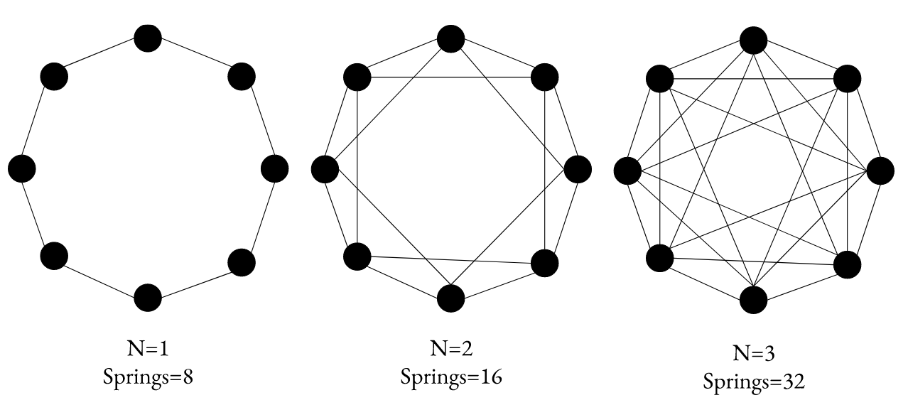
Figure 1: By connecting neighbors up to the nth, more internal springs exist to maintain structural stability.
While this method may not be optimal for modeling every mesh, it is a mesh independent approach which has displayed admissible results.
Collision Handling:
Collision detection is implemented using raycasting to prevent mesh penetration and ensure collision-free movement. Each point mass stores its previous and current position. A ray is drawn from the previous position to the current position. We then check if this ray intersects with any primitives within the distance the point is traveling. If it does collide, we set the point-masses’ current position to be its previous position.
Deformation Constraint:
To prevent over-deformation, we ensure that the springs do not compress past a fixed percentage of its rest length. In the case that point-masses are too far apart or too close together, we calculate the appropriate correction vector and add it to the point-masses.
Plastic Deformation:
After building out the above components, we were able to simulate elastic collisions for 3D meshes. To expand this for plastic deformation, we modified our deformation correction algorithm. In the case that a spring does exceed its “elastic limit”, we modify the rest-length of the spring based on Hooke’s stress-strain laws to dynamically update the spring’s new rest length when a spring’s behavior is plastic.
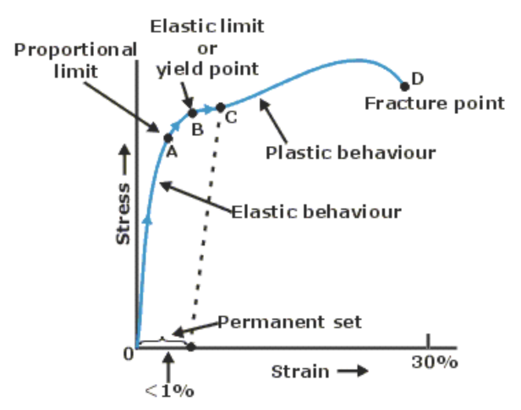
Figure 2: Stress-Strain Curve of a Typical Metal
Model Update:
After the point-masses’ new positions have been calculated, we use the mapping of point-mass to vertex created during the initialization step to reflect these changes. In order to ensure Unity’s lighting engine works as intended, we must recalculate the new normals of each triangle within the mesh. Unity’s built in UpdateNormal() mesh function was not satisfactory for this project as it prioritizes efficiency and lacks any means of refinement or smoothing, resulting in a not so smooth sphere. Meshes sometimes don’t share all vertices. For example, a vertex at a UV seam is split into two vertices, so the RecalculateNormals function creates normals that are not smooth at the UV seam.
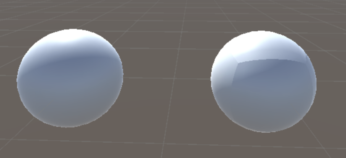
Figure 3: Unity mesh.recalculateNormals() flaws
To fix this, we built a very simple but sufficient algorithm to recalculate the normals seamlessly. This algorithm iterates over the vertices of a mesh, merging duplicate vertices based on their hash codes while updating the triangles to maintain seamless connectivity. After merging, it recalculates the normals of the merged vertices, then assigns these recalculated normals back to the mesh while restoring the original triangles.
Interactivity:
In order to observe forces applied in different directions other than gravity, we decided to create our simulation in a zero-gravity environment with interactivity through WASD keys. Pressing a direction key will add an acceleration to the mesh in the direction of the key. Then, by enclosing the mesh within four walls with colliders, we can move the object around and witness its reaction to collisions on all sides of the mesh. In addition, prior to starting the simulation, the user can input the parameters of the spring-mass system and the desired level of bending.
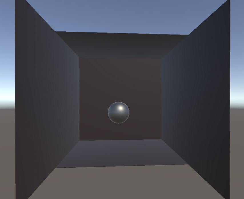
Figure 4: The simulation set up in Unity
Challenges:
One challenge we encountered was dealing with Unity’s triangle meshes. In order to bind point masses and springs properly, we had to create many dictionaries to store vertex information such as their index inside the vertex list and their neighbors. An interesting discovery that we made along the way was that Unity actually has duplicate vertices for each triangle. A cube would intuitively have 8 vertices, however, in Unity, a cube has 24 vertices (6*4) since every face needs 4 vertices for surface normals and UVs. Therefore, we needed to keep track of duplicate vertices and ensure that a change to one point mass is reflected on the multiple vertices that belong to it.
Another challenge we faced was our meshes deforming in extreme ways, resulting in occasional undefined behavior and random mesh explosions. In order to fix this, we took inspiration from the ClothSim project and set a maximum deformation from rest length for each spring.
The last major challenge we faced was maintaining structural integrity. We initially believed that with a strong enough spring constant, we would be able to maintain hollow 3D objects without any internal springs. We then discovered that this did not prevent point masses from moving inwards when the spring rest length does not change. As a result, we designed our bending spring algorithm by connecting the 1st to nth neighbor of each point mass with a spring.
Results:
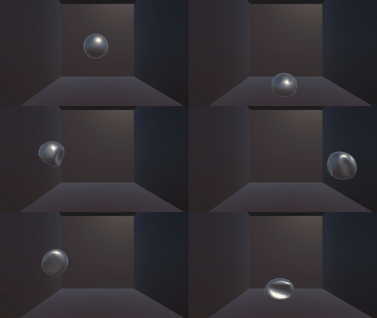
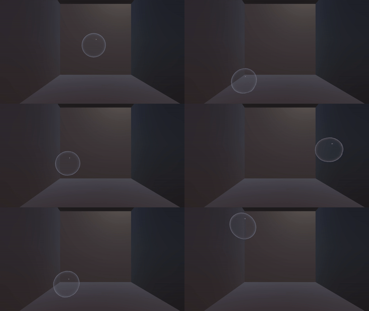
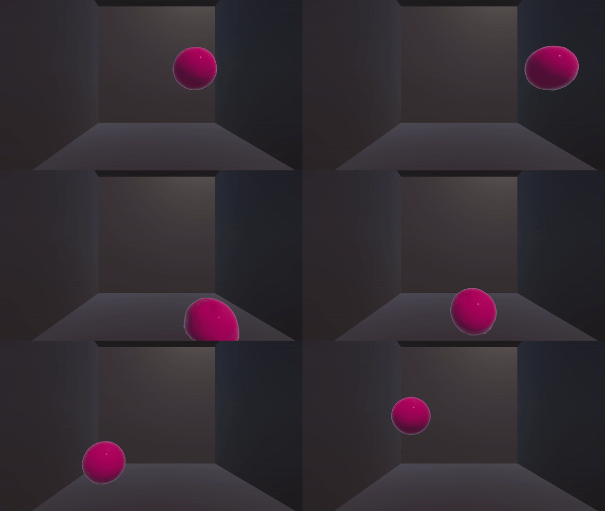
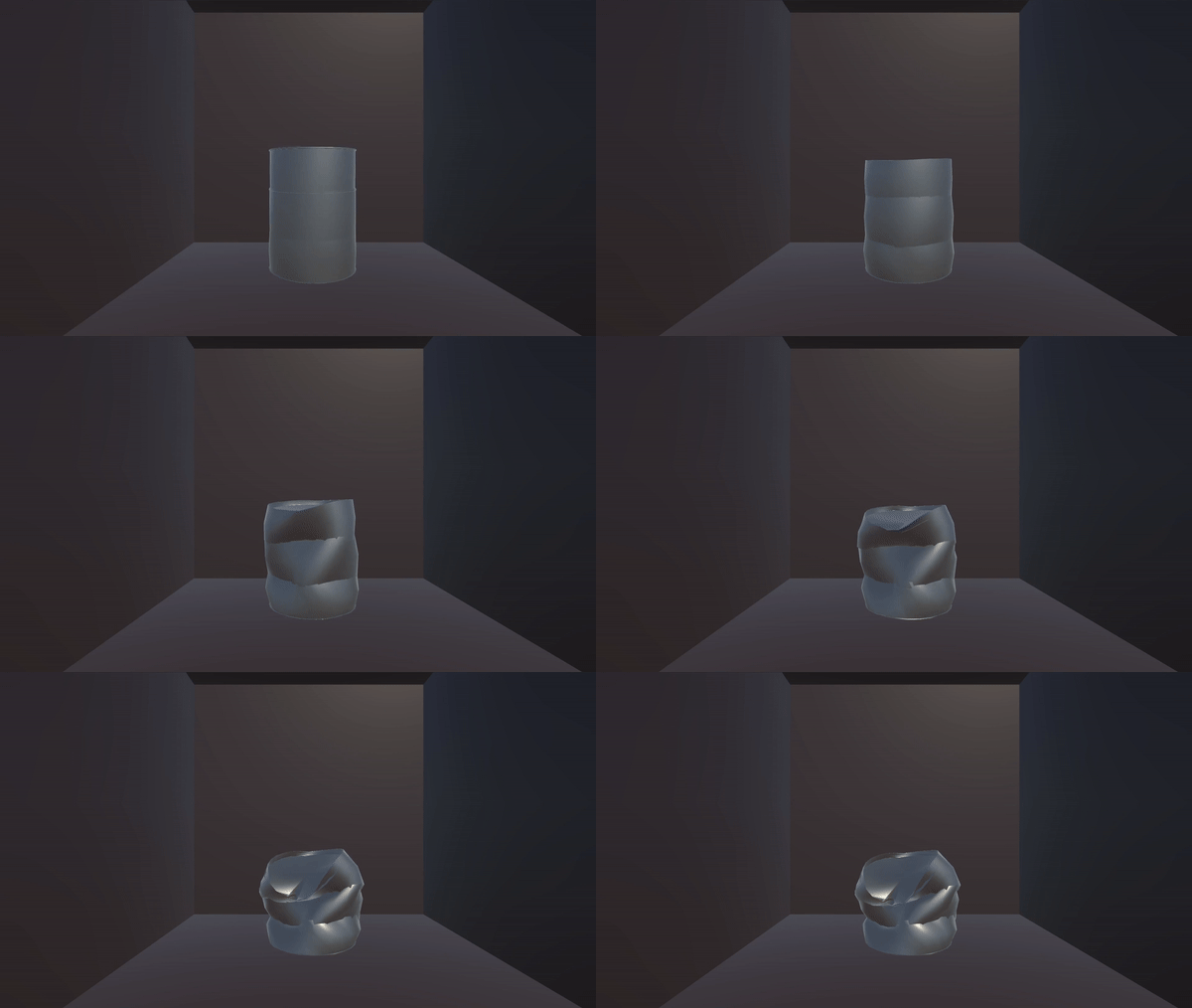
In these videos, the object is being controlled by using WASD keys to apply forces in different directions.
Metallic Ball
Bubble
Bouncy
Can Crushed Downwards Plastic Deformation
Can Crushed Left Plastic Deformation
Approach 2: Direct Mesh Transformation
Technical Approach:
With this approach, we directly accessed the underlying mesh structure of the object and recalculated the positions of the mesh’s vertices. Unity has robust Mesh functionality, which allows for mesh collision and rendering. The basic idea that we started with was a top-down force direction (i.e. a uniform force along the Y-direction). This way, we defined a downward force vector from the centroid of the mesh’s vertices, and an adjustable radius of impact, such that vertices within the radius from the centroid are affected more to simulate direct impact. As the force from the centroid gets applied onto the objects, the centroid gets recalculated, thus shifts down, and the process repeats for subsequent frames.
Position Perturbation Clamping:
The problem that we came across during the testing was the unbounded additive force causing the vertices to fly off the object’s shape significantly. Initial attempts to lower the force values failed, as the force would over time become unstable. To mitigate, we decided to use a clamping function.
Since we realized that simply lowering the force across time steps did not give a favorable output, we kept track of the original positions of vectors and calculated the residual vector between the new positions and original positions: r = v_new - v_original. Then, we generated a perturbation factor to limit the amount of change between the new and original vectors by first applying a clamping function $f(x)$ to the residual vector’s norm. This new perturbation factor is then applied to the maximum deviation amount (set by the user) to adjust the amount of change to apply to the vertex original positions.
Here we decided to use $f(x) = \frac{x}{\sqrt{c + x^2}}$ as the clamping function, which has the nice feature of approaching 1 in the limit as $x$ approaches infinity. The parameter ‘c’ can be used to slightly decrease the rate of clamping for small values of $x$.
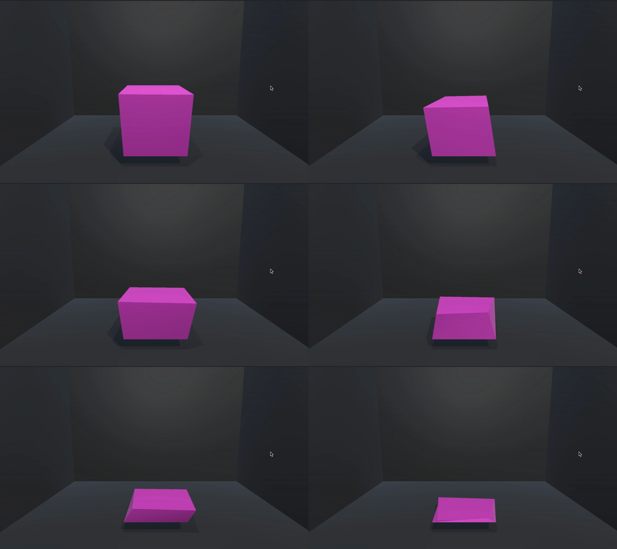
As a side note, modifying this function can significantly change the behavior of the animation and achieve some interesting results. By using $f(x) = \sin(cx)$, we get this funny bobbing cube:
Addressing Feedback Loop Errors:
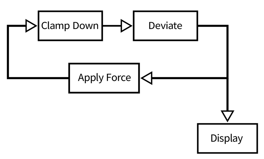
However, we quickly realized that this method made the animation look really jagged when combined with the deformation logic. The issue here was that the code made our clamped residuals be processed by the clamping function yet again, to only get enlarged by the applied forces. Any attempt to change the force starting values failed yet again. We realized that the root cause of the problem was that code workflow continually performed a feedback loop (see below), compressing and immediately enlarging the residual vectors in every frame, causing it to jitter:
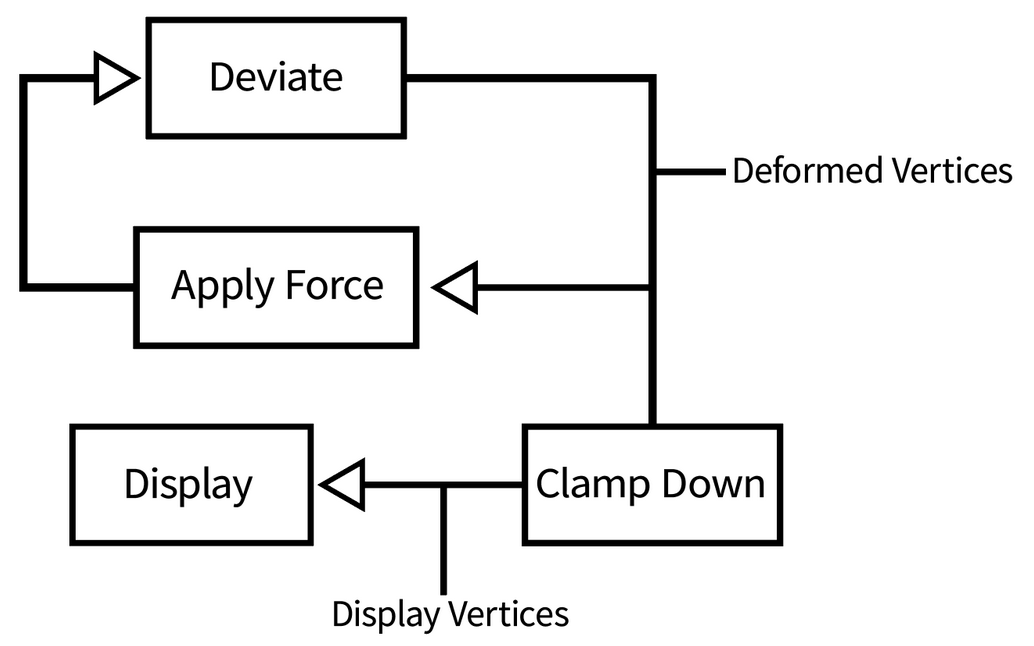
To combat this, we decided to use two sets of vertices: an array of vertices for the force deformation and another for displaying purposes. The display vertices were simply clamped down versions of the deformed vertices. This approach helped us maintain the smoothness of the animation because the feedback loop would only apply distortions to the deformed vertices array, and the display vertices array would clamp the ever growing magnitudes of the deformed vertices. This helped us get rid of the jaggedness, and helped us control the contribution of the force on the animation. See the updated logical feedback loop in the diagram below.
Identical Vertex Group Mapping
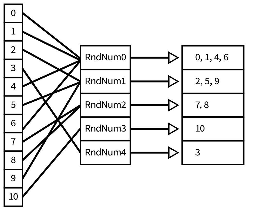
Unity stores a copy for each identical vector, so a random change in one would not be the same as in the other, forming gaps. To fix the gaps between the triangles that formed as a result of deformations, we coded up an API on top of Unity’s mesh structure to edit the vertices directly. We grouped all similar vertices together using a random index. The diagram below shows the mappings between Vertices’ indices and the random index values.
Custom Meshes and GameObjects:
When directly modifying the meshes of GameObjects, we ran into the problem that the approach was too simplistic and looked too linear to look realistic, particularly for the default shapes in Unity which have a fixed minimal number of vertices. We experimented with custom procedural cubes and spheres (source), though the resources online referenced children objects for each face with separate mesh colliders. Significant refactoring allowed for a unified cube mesh object with tunable side length, and intricate meshes with more vertices and shorter edge lengths experienced more randomness. Additionally, we experimented with upsampling the meshes via Catmull-Clark subdivision on pre-existing mesh objects and Unity assets to create more intricate meshes and randomness in deformation, but this came with the issues of deforming materials and also introduced more complexity and lag when running the animation.
Final Additions:
As a final touch to deformation simulations, we have added a mapping of random deviation vectors to display vectors to distort the shape a bit more and add noise during the deformation animation, as would be expected in a real crushing. The API for identical vertex grouping also helped prevent the formation of gaps.
To add support for dynamic and multi-axis forces, we decided to introduce a force direction vector instead of the hard coded effects in the Y-values. The force direction was expressed as a vector, which helped us filter out the forces accordingly by using the inner product of residual vectors with force/deformation unitary vectors. We also used linear algebraic transformation to enable the user to select the axis of deformation dynamically. This was done by using filtering binary vectors which helped isolate the entries in vectors that would need to be affected. To add interactivity, we added the ability for users to dynamically adjust the axis of deformation using WASD, and also start the animation/reset the animation to its original state using the mouse buttons.
Results:
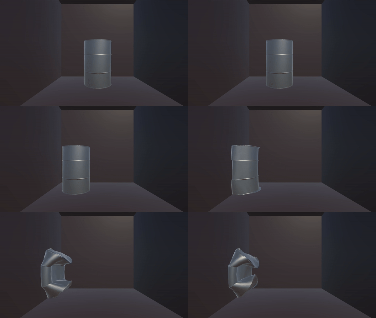
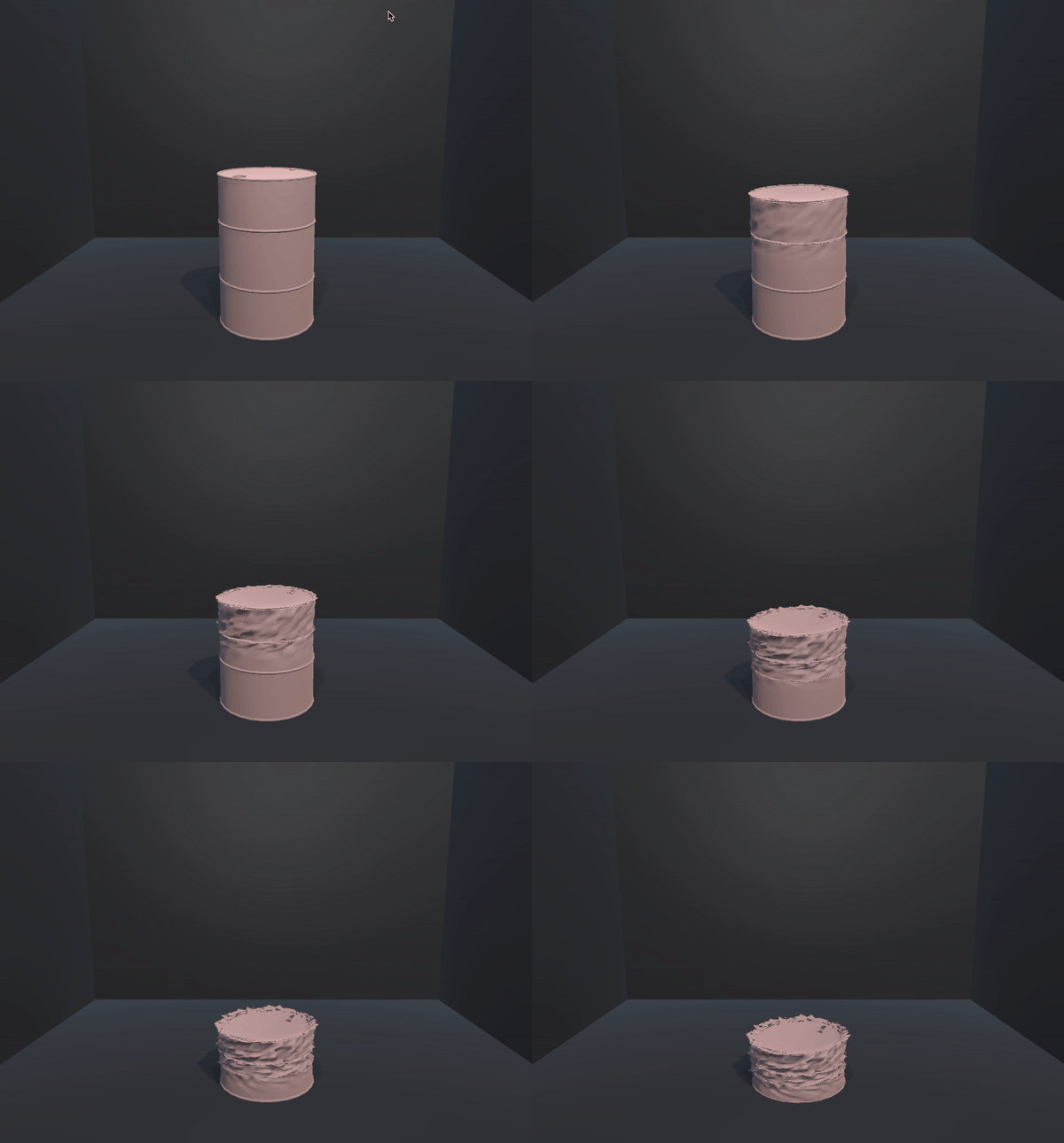
Barrel asset, standard downward force
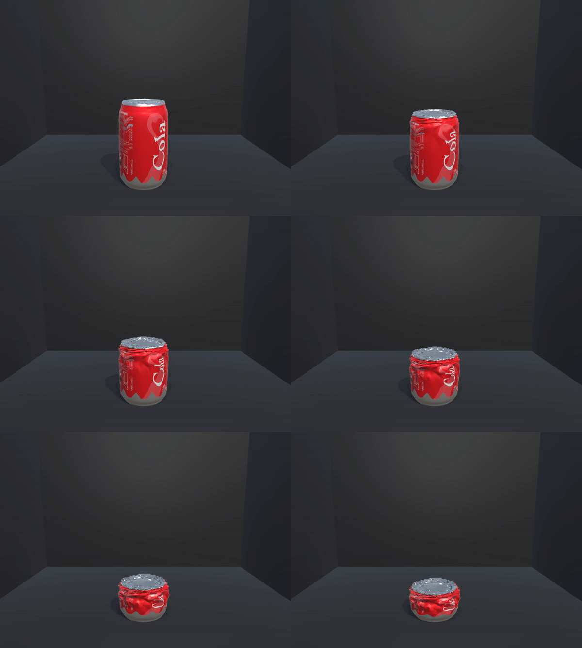
Soda can asset, after 1 iteration of Catmull-Clark subdivision - more realistic:
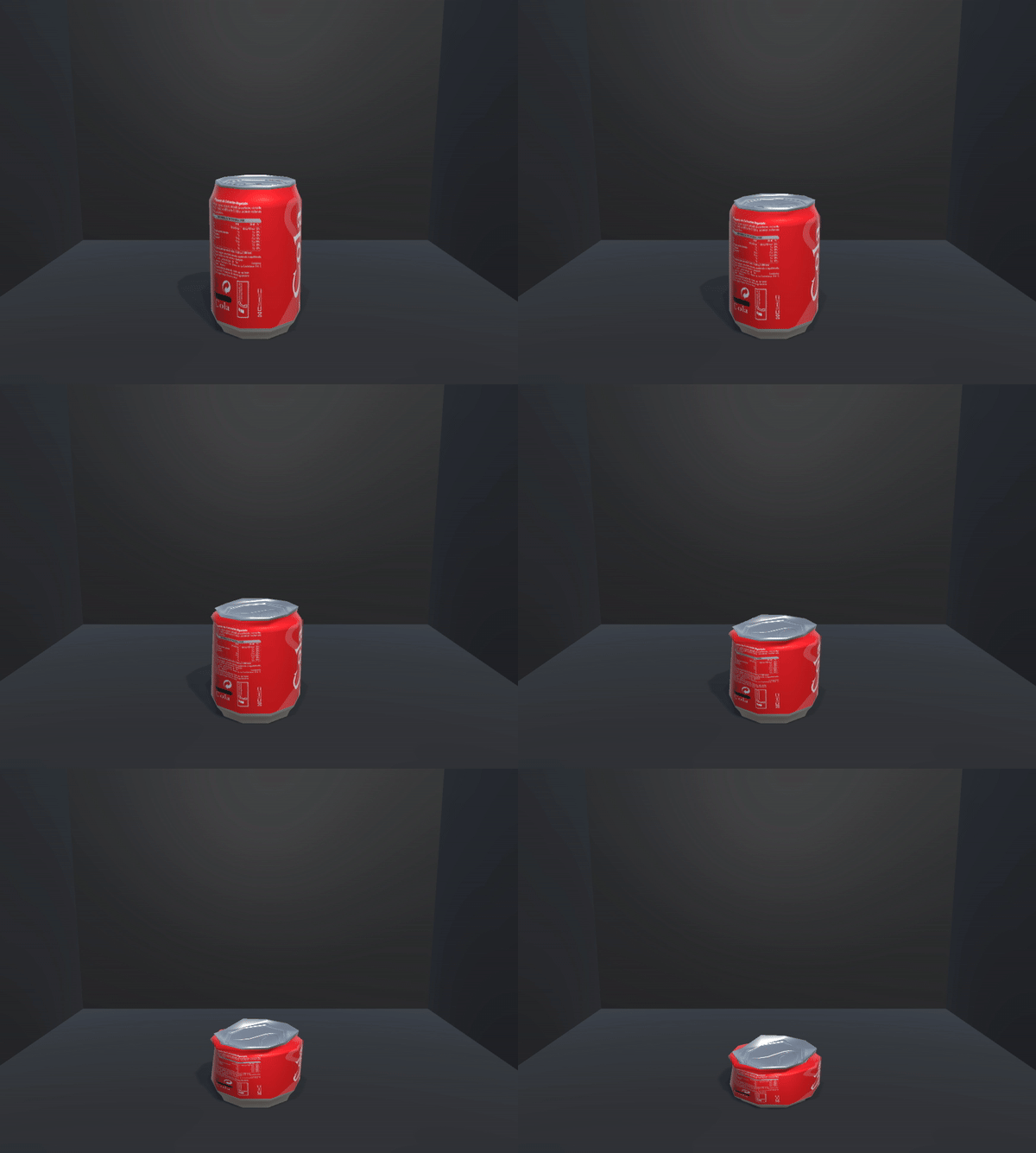
Soda can asset (default) - poor deformation:
Cube mesh with 50 vertices per side, mid-animation force direction change via WASD keys:
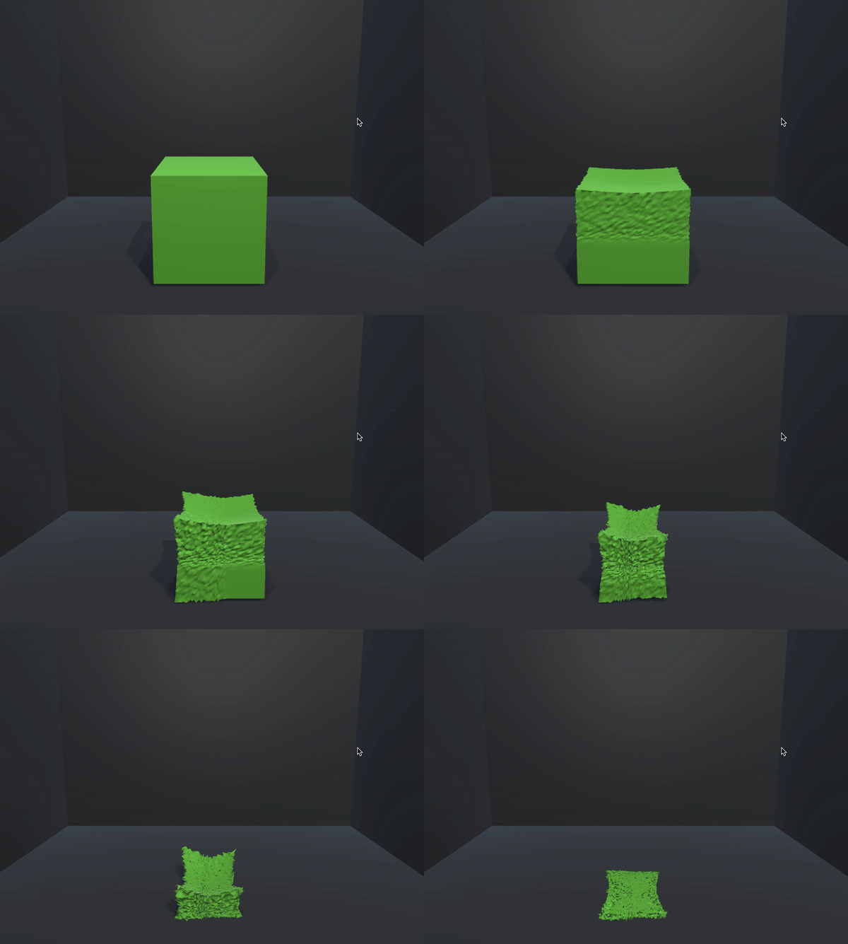
Cube mesh with 20 vertices per side:
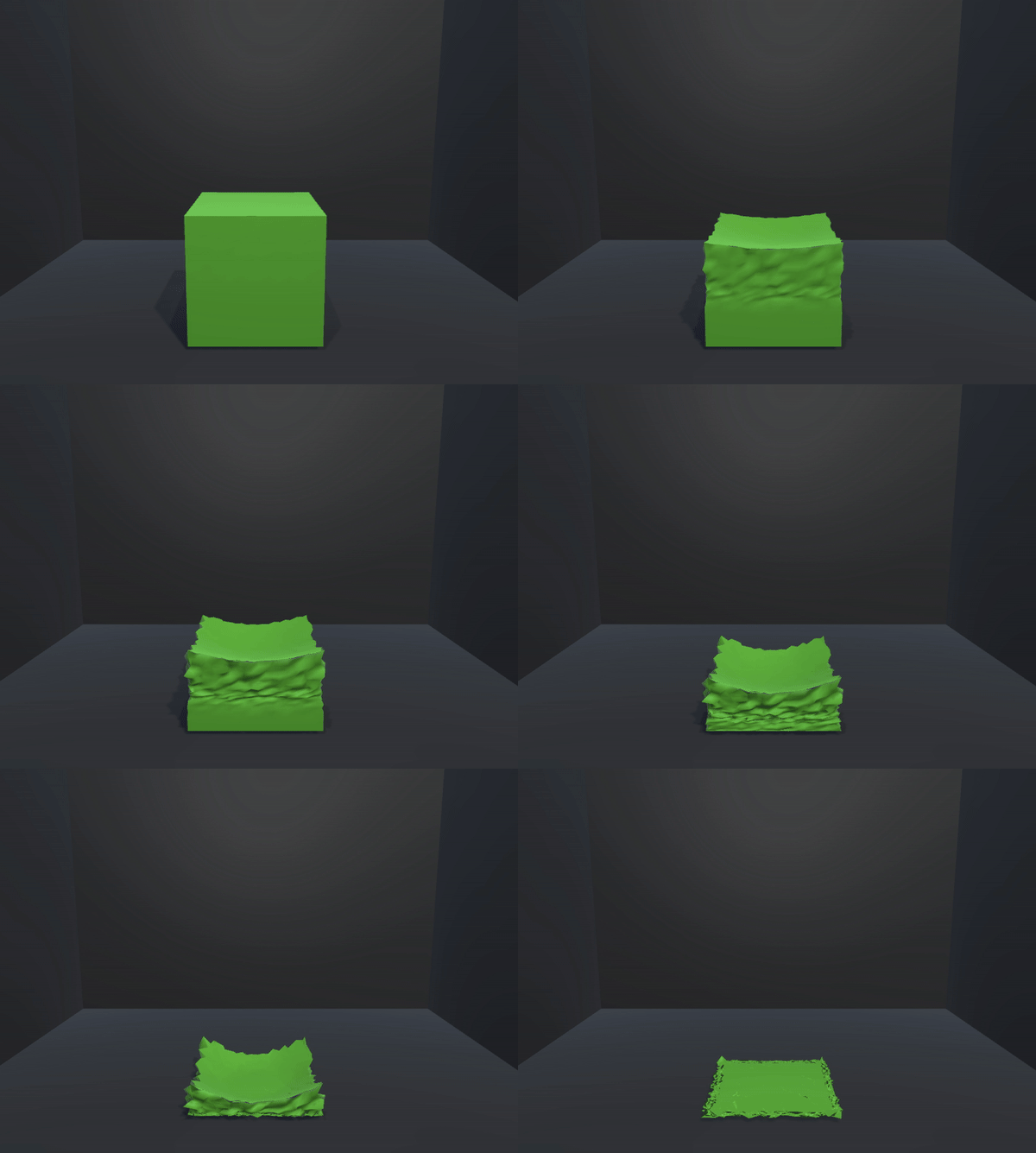
Cube mesh with 10 vertices per side:
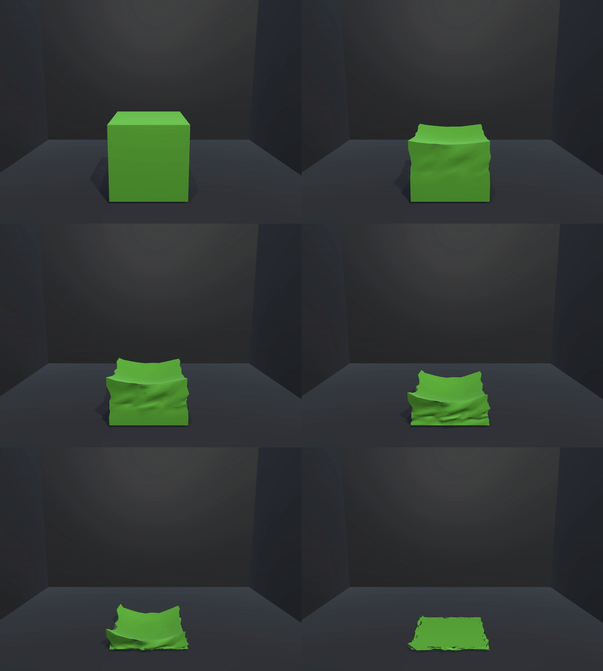
Default Unity cube - poor deformation:
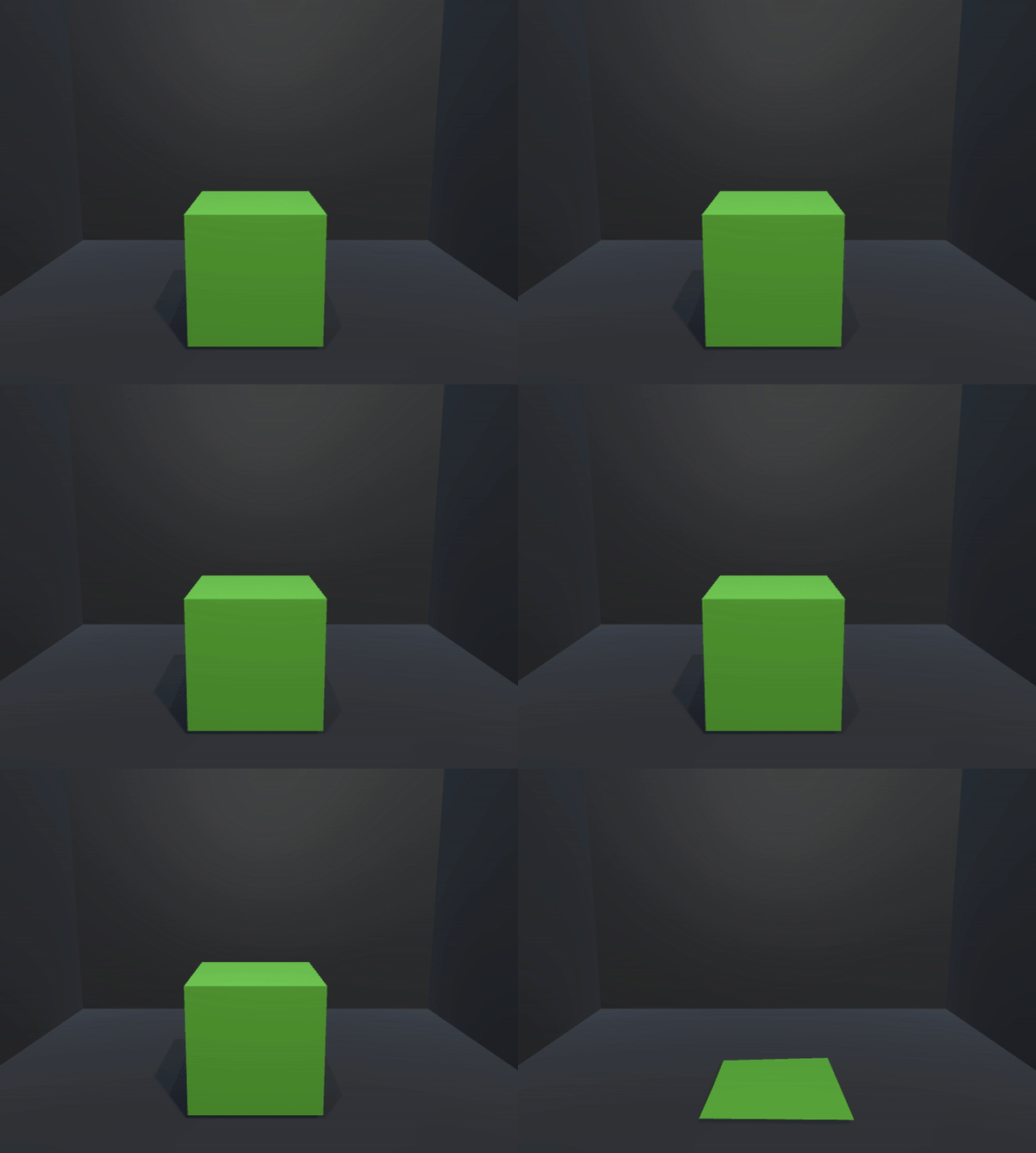
What We Learned
In this project, we learned about simulating soft-body physics within the Unity game engine by exploring and tinkering with the Unity Mesh and collision systems. In the spring mass system approach, we gained insight into representing soft bodies as collections of interconnected point masses and springs, allowing for realistic deformations and dynamics. We also acquired knowledge on efficiently organizing and processing vertex data of a mesh to interact with the spring-mass system and enabling plasticity. In the direct mesh deformation approach, we experimented with the fluidity of animation and difficulty in modifying intricate mesh vertex positions. Additionally, we explored techniques for handling collisions, enhancing the realism of the soft-body simulation. Lastly, we practiced incorporating mesh manipulation functionalities to create interactive and visually compelling soft-body simulations.
References/assets
- HW 4: ClothSim
- Unity Mesh API: Script Link
- Cam and Barrel assets in Unity:
- Sebastian Lague’s guide to procedural mesh generation in Unity: YouTube video
- Adjusted his classes to fit our deformation model by unifying the mesh into one MeshCollider, instead of six separate meshes for each face
- Catmull-Clark in Unity: Asset Link
Contributions
-
Mukhamediyar Kudaikulov: Background research, mesh modeling, direct mesh deformation model and custom direction/force amount modifications, applying direct mesh deformation model to custom meshes, mesh subdivision
-
Rishi Khare: Project ideation + direction, background research, Unity mesh modeling, direct mesh deformation model, applying direct mesh deformation model to custom meshes, procedural mesh generation, early setup work in spring mass
-
Aniketh Prasad: Background research, spring mass in Unity, spring mass system plasticity modification, applying spring mass system to custom meshes and GameObjects, procedural mesh generation
-
Alson Chan: Background research, seamless mesh normal calculation algorithm, interactivity ideation, demo video editing, presentation